VERIFIED VIEW MONTAGE METHODOLOGY
APPENDIX
VERIFIED VIEW MONTAGE METHODOLOGY
A Verified View Montage (VVM) - also known as an Accurate Visual Representation (AVR) or Visually Verified View - is a highly accurate, technical image that combines professional site photography and on-site viewpoint and reference markers surveying with 3D computer-generated imagery (CGI) to show exactly how a proposed development will appear in its surrounding environment. These images are "verified" because they are technically defensible and can be cross-checked against real-world survey data.
Verified views are essential for contentious or sensitive planning applications (especially in the UK and Ireland):
- Planning Submissions: Providing planners, inspectors, and objectors with an accurate evidence base.
- Visual Impact Assessment: Helping to evaluate how a new project fits into the existing landscape or streetscape.
- Transparency: Eliminating guesswork, allowing stakeholders to see a realistic, objective representation.
1. Purpose and Scope
This document defines the methodology used for the production of Verified View Photomontages for planning, design, and visual impact assessment purposes.
The process is aligned with the Landscape Institute's Visual Representation of Development Proposals (2019) and other established industry best practices.
The primary objective is to ensure that all outputs are:
- geometrically accurate,
- geographically and survey referenced,
- reproducible and verifiable,
- suitable for planning submission and stakeholder review.
2. Software
The following software tools are used throughout the workflow:
- 3D Modelling software: we mostly use Autodesk 3ds Max or Lightwave 3D for modelling, scene assembly, camera matching, and spatial integration.
- Physically based rendering engines such like Corona Renderer, V-Ray or equivalent software.
- Adobe Photoshop – compositing and final photomontage post-production.
- Optional: aerial photogrammetry software where drone imagery of the site can be obtained.
The workflow supports multiple CAD/BIM formats including Revit, SketchUp, Archicad, IFC, DWG, PDF, and other client-supplied datasets.
3. Photography
Site photography is conducted using:
- Sony Alpha ILCE-7RM3A
- Fixed focal length lenses: 50mm, 24mm or 14mm (used only in exceptional circumstances where a wider field of view is required).
For each viewpoint, two photographic versions are captured (24mm and 50mm), allowing selection of the most appropriate composition depending on contextual clarity and planning requirements.
The Landscape Institute's Visual Representation of Development Proposals (2019) states that a 40° horizontal field of view captured using a 50 mm lens most closely represents normal human visual perception and is recommended for the verified view photomontages.
A 24mm - wide angle is selected for the photography to provide more information on the context around the proposed development and in the close-up views where the proposed development doesn’t fit into the view. The horizontal field of view of these photographs is 74°. In the cases where the wide lens is used, there should be an indication of 40° field of view, which is shown at the bottom of all the views.
When printed at A3 size, the recommended viewing distance is approximately 500 mm for images captured using a 50 mm lens and 300 mm for images captured using a 24 mm lens.
Capture methodology:
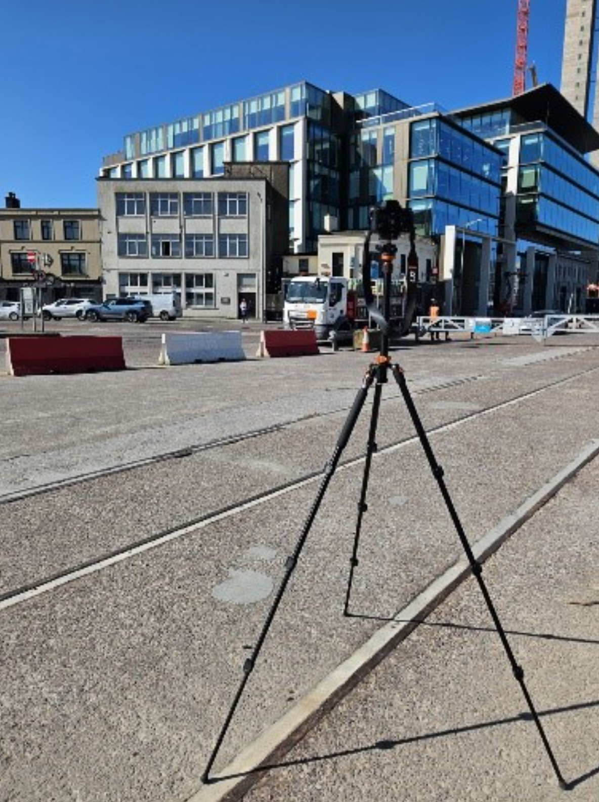
- Use of tripod with integrated spirit level to ensure a level horizon.
- Use of laser measuring device to record camera height above ground level.
- RAW image capture for maximum post-production flexibility.
- Controlled exposure settings based on site conditions.
- Photographs are captured at approximately 10° intervals, providing coverage of up to 120° and allowing the most suitable viewpoint to be selected during subsequent processing.
4. Essential Metadata Capture
To accurately record metadata for Verified View Montages all technical details of site visit are documented to be used in rendering suite. This is step by step workflow we follow:
- Clock Calibration. Before heading to site we synchronize camera's internal clock with survey equipment and GPS clock to ensure exact alignment with solar calculation software.
- Record Weather Conditions:
o Sky Condition/ Cloud Cover. We log the description of cloud types and percentage of coverage (e.g., clear sky, overcast, broken clouds) which dictates direct sunlight vs diffuse ambient light.
o Visibility: we assess the air clarity (e.g. clear, hazy, misty) to account for atmospheric attenuation on long-range views.
o General Description is recorded: Short descriptive text accompanying the viewpoint metadata (e.g., "bright sunny intervals", "even overcast light" or "clear visibility"). - Spatial & Survey Coordination: we document the precise XYZ coordinates of the camera's optical node and target points retrieved via an RTK GNSS receiver.
5. Post Site Work on the Photographs
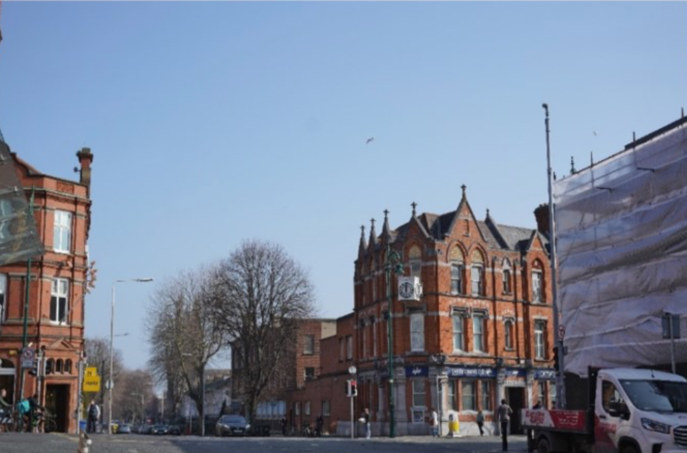
Following the site visit, the photographs are reviewed to determine the most appropriate viewpoint and focal length for representing the proposed development. The selected baseline photos are then issued to the client for confirmation. Once confirmed, the photos would be post-processed and tidied up – minor transient elements, such as litter, may be removed. Vehicle registration plates and identifiable faces are obscured to comply with GDPR requirements.
6. Survey Data and Input Information
Base spatial information is typically provided by the client in the form of:
- CAD drawings
- topographical and contextual site data
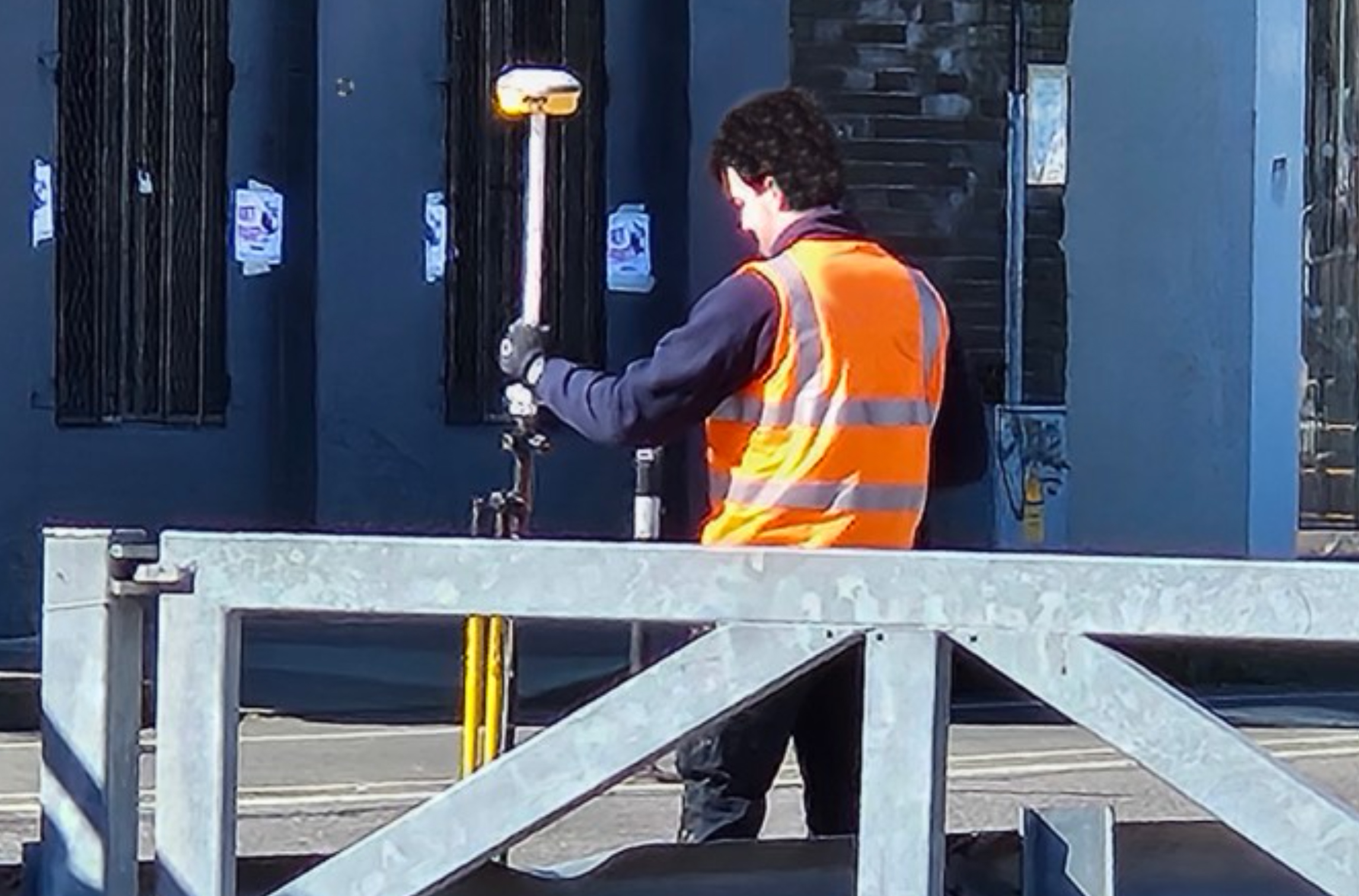
- Additional site data is captured by our on-site surveyor using GNSS surveying equipment: GeoMax Zenith60.
Each photographic viewpoint is recorded with precise:
- horizontal coordinates
- elevation data
- spatial reference information
This ensures accurate georeferencing of all camera positions within the 3D environment.
Viewpoint locations are indicated in the Viewpoint Map provided with Verified View Montage booklet, viewpoint coordinates and information on photography is under each photo.
7. Camera Positioning and Georeferencing
Following site photography and surveying, spatial data is provided in the form of:
- DXF file containing surveyed camera positions (GNSS-based)
- TXT file containing coordinate and elevation data for each viewpoint
Workflow in 3D environment:
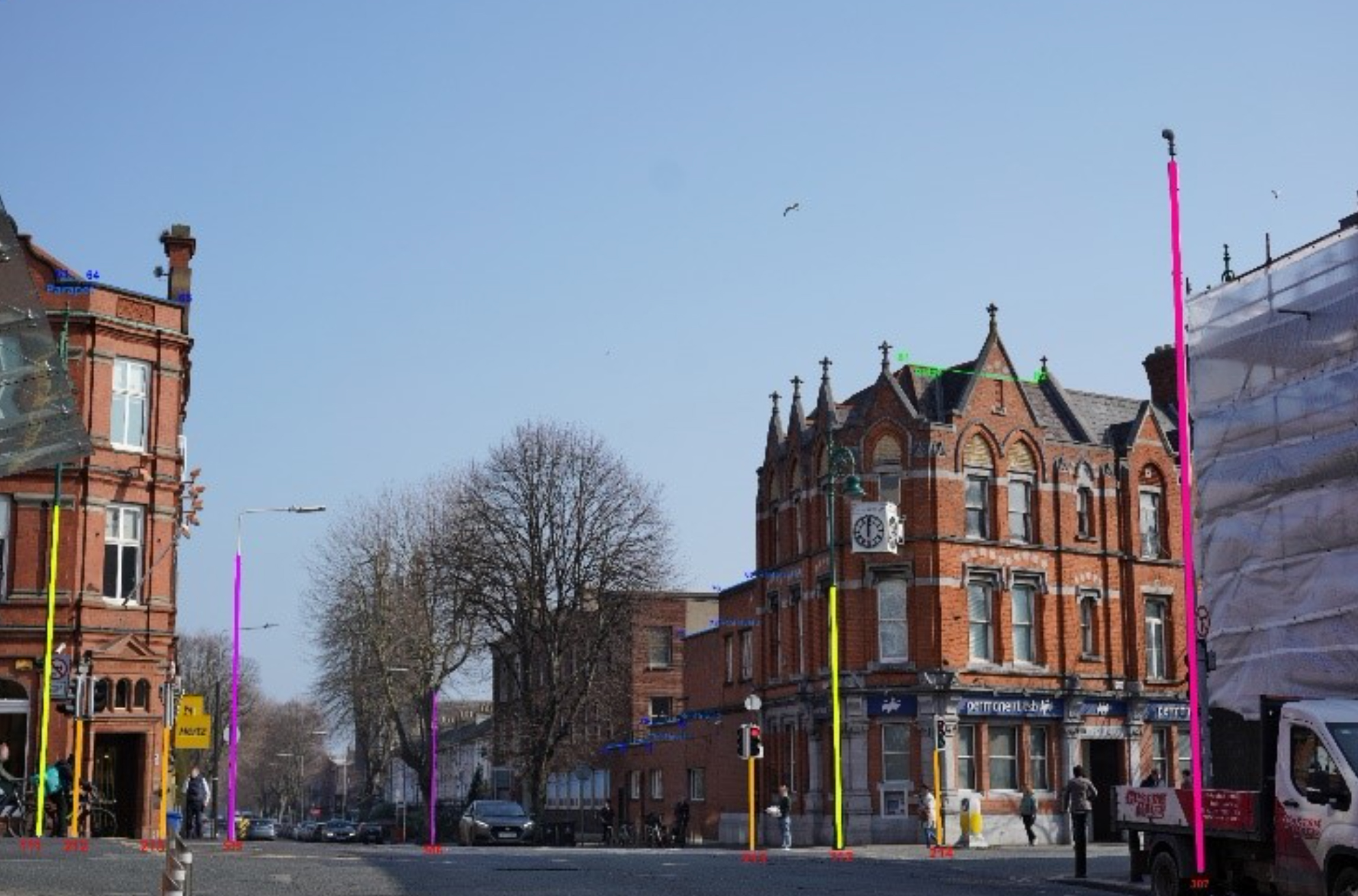
- Import DXF camera positions into Autodesk 3ds Max.
- Import client-provided DWG survey and topographical data.
- Align all datasets within a unified real-world coordinate system.
- Construct spatial reference geometry based on identifiable site features.
- Generate virtual cameras using EXIF-derived camera parameters.
- Position cameras at surveyed coordinates.
- Refine orientation by matching:
o photographic background imagery
o surveyed site reference points visible in both the photograph and the 3D model - Iteratively adjust camera alignment to ensure high spatial accuracy.
All scenes are constructed in real-world scale units.
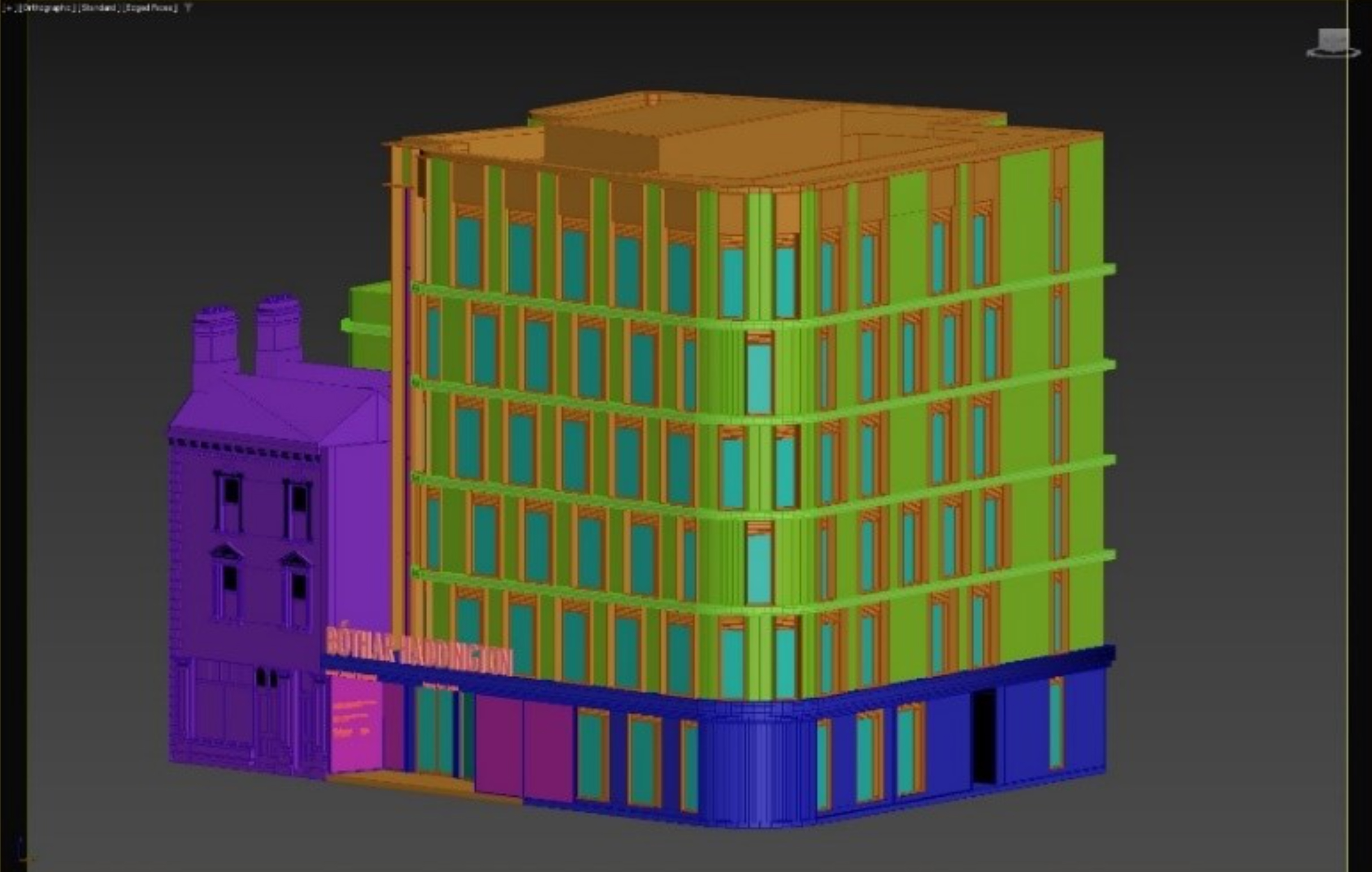
8. 3D Model Development
A highly detailed model is created internally based on architectural drawings and design specifications.
All models are constructed in true scale and integrated into the georeferenced environment.
9. Representation of Proposed Landscape
Where proposed landscaping is included within a development, it is illustrated in the verified view photomontages using landscape architects' drawings, including soft and hard landscape proposals, planting schedule plans, and boundary treatment plans.
Where required, photomontages may be prepared to show the proposed landscape at different stages of establishment, typically:
- Post-construction (Year 0)
- Year 5
- Year 15
The representation of planting growth is based on the information provided by the design team and is intended to illustrate the likely appearance of the landscape at each stage.
10. Lighting and Environmental Simulation
Lighting conditions are configured to replicate real-world photographic conditions.
- Sun position is calculated based on:
o exact date and time of photography
o geographic location of the site
This ensures accurate reproduction of:
- shadow direction
- solar elevation and azimuth
- environmental lighting conditions
11. Rendering Process
Photorealistic rendering is performed using:
- Corona Renderer, V-Ray or equivalent rendering software.
Render outputs include:
- physically accurate lighting simulation
- correct material response
- high-resolution image generation for compositing.
12. Photomontage Creation and Post-Production
Final compositing is carried out in:
- Adobe Photoshop
Post-production process includes:
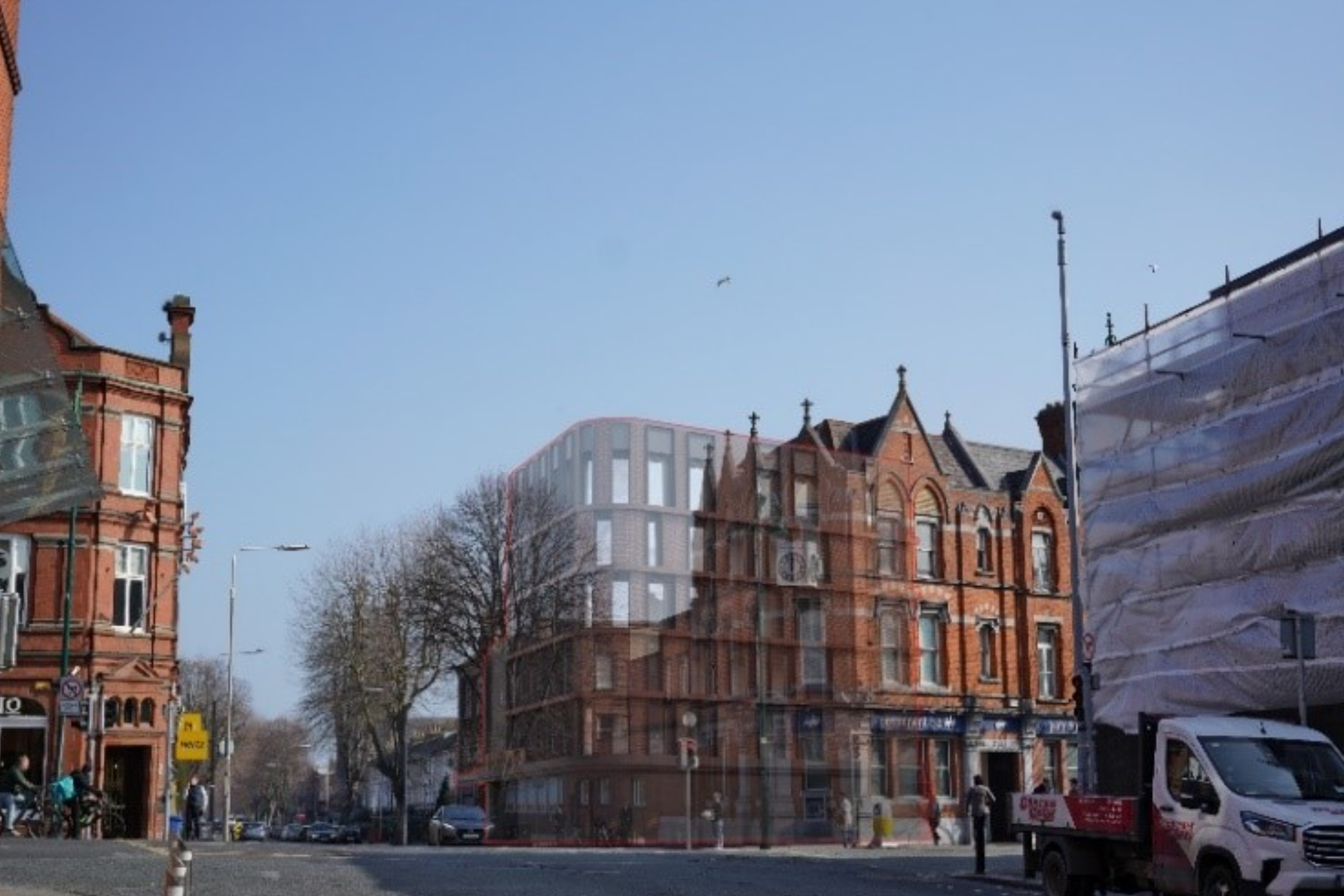
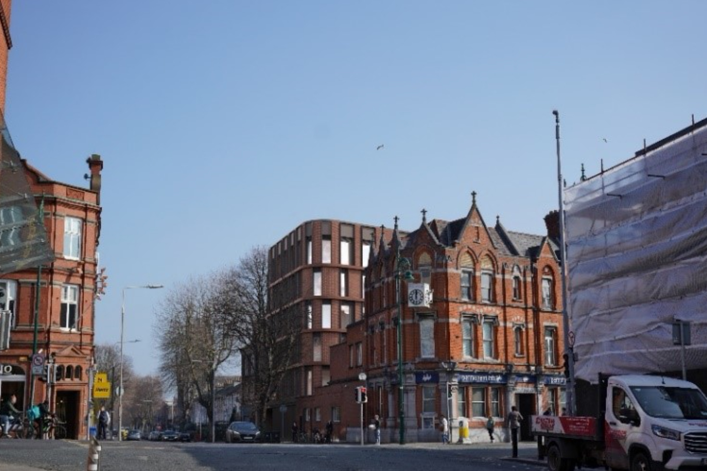
- integration of rendered CGI elements into the site photography. This includes the accurate positioning of the rendered model and the masking of foreground features (such as buildings, trees, and street furniture) to ensure correct visual depth and occlusion relationships
- precise alignment refinement where required
- exposure, contrast, and colour matching
- atmospheric blending (depth, haze, environmental consistency)
- final visual verification of realism and coherence
13. Quality Assurance and Verification
Each output is subject to quality control checks including:
- spatial accuracy of camera positions
- correct perspective alignment
- consistency with survey and GNSS data
- accurate sun and shadow matching
- visual continuity between CG and photography
All deliverables are reviewed to ensure compliance with Verified View principles and planning requirements.
14. Output Deliverables
Standard deliverables include Verified View Montage booklet that containing:
- Baseline Photographs
- Verified View Photomontage images (single-frame)
- Supporting viewpoint and camera metadata (if required)
- Technical documentation or reference information
15. Optional Aerial Photogrammetry (Drone Survey Support)
Where site conditions, weather, and airspace permissions allow, aerial photography may be conducted using a drone. This step is optional and used only when available.
Aerial imagery may be processed to enhance spatial understanding of the site.
Workflow:
- Capture aerial photographs using drone platform
- Generate photogrammetry-based 3D model (point cloud / mesh)
- Import resulting model into modelling software.
- Use the model as an auxiliary reference for:
o improved camera alignment accuracy
o validation of site geometry
o enhanced spatial verification
Note:
This method is supplementary and does not replace primary surveyed data or official topographical information. Its application depends on project feasibility and availability.

